Understanding Gating Systems in Casting: Types and Design Considerations

Gating System Design
In the realm of sand casting, the design of the metal pouring system is of utmost importance. Its layout not only impacts casting quality but also reduces metal wastage. In this article, we will delve into the intricacies of the gating system in the casting process.

What Is a Gating System in Casting?
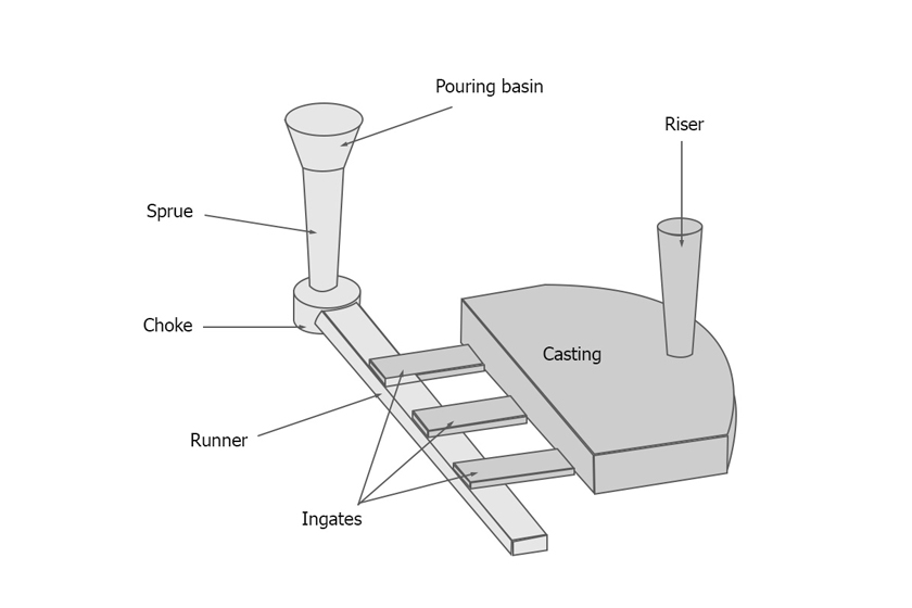
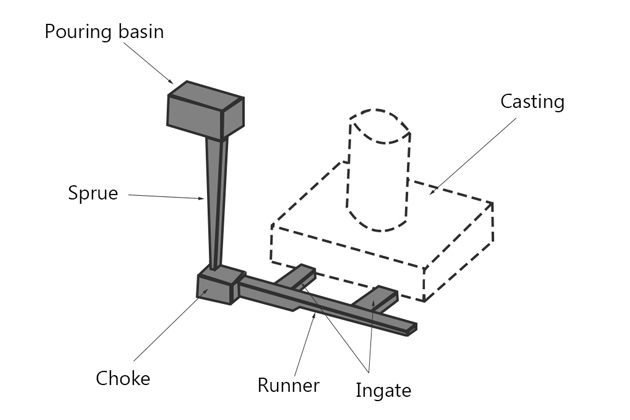
Within the metal foundry, the gating system in casting serves as the conduit through which molten metal is directed into the mold cavity. Metal flows from the pouring basin to the sprue, continues through the runner and gates, ultimately entering the mold cavity.
Designing a Gating System: Factors to Consider
Designing an effective gating system necessitates meticulous attention to technological requirements, materials, and the nature of the castings. This system plays a pivotal role in determining the rate at which metal flows into the mold cavity.
- Flow Rate Control: The gating system’s design must strike a balance between too fast, risking corrosion, and too slow, causing premature cooling of the metal, which directly affects casting quality.
- Shape and Size: Proper arrangement of the gating system’s shape and size during mold creation is essential. An improperly designed gating system can result in severe casting defects.
Functions of the Gating System in Sand Casting
The gating system in casting serves four primary functions:
- Efficient Metal Filling: It ensures the mold cavity is filled rapidly without needing to increase the metal temperature.
- Smooth Metal Flow: The system minimizes turbulence, reducing air trapping during casting.
- Temperature Control: The gating system allows for controlled cooling, preventing shrinkage in casting parts and facilitating the removal of metal impurities.
- Impurity Removal: It aids in removing metal impurities.
Design Requirements of the Gating System
A well-designed gating system should fulfill the following criteria:
- Precise Metal Flow: Ensures a smooth, non-impactful, and steady metal flow.
- Impurity Prevention: Prevents slag, impurities, and gases from entering the mold cavity.
- Efficient Filling: Quickly fills the mold cavity without diluting the metal excessively.
- Temperature Control: Maintains stable metal cooling within the mold cavity.
- Metal Conservation: Minimizes metal wastage.
- Ease of Disassembly: Facilitates easy disassembly after the casting has solidified.
- Economic and Maximizes Yield: Optimizes economics while maximizing casting yield.
Incorrectly designed gating systems can lead to various issues, including oxidizing metals, mold corrosion, object shrinkage, metal penetration of mold walls, uneven casting cooling, and more.
Components of the Gating System
The gating system in sand casting comprises several key components:
- Pouring Basin or Pouring Cup: This funnel-shaped inlet, situated atop the system, allows metal to be poured from ladles into the mold. It regulates the metal flow rate, reduces turbulence at the sprue entrance, and separates sediment and slag.
- Sprue: A vertical passageway leading from the pouring basin down to the runner and gates. Metal descending the sprue experiences a drop in pressure but an increase in speed due to gravity. The sprue’s cross-section can be circular, square, or rectangular, with the bottom end connecting to the runner after a right-angled turn known as the sprue well.
- Runner: A horizontal channel connecting the sprue well to the gates. It facilitates the smooth flow of molten metal from the sprue to appropriately fill the mold cavity. The runner also serves to reduce the velocity of the liquid metal as it free-falls from the high-speed sprue, ensuring a steady flow and preventing slag from entering the cavity.
- Ingate (or Gate): Located at the end of the path where the mold cavity begins, the ingate guides the liquid metal from the runner into the mold cavity. The size and shape of the ingate must match the casting’s characteristics, with different types of gates for varying solidification rates.
Types of Gates in Casting
Gates can be categorized into three main types:
- Top Gate: Positioned in the cope mold part, it tends to generate high metal flow turbulence and may result in a poorer casting surface.
- Bottom Gate: Located in the drag mold part, it allows liquid metal to fill the lower portion of the mold cavity and gradually rise into the mold wall. Bottom gates experience less chaos and sand erosion but can face challenges if the metal solidifies prematurely.
- Parting Line Side Gate: Positioned along the parting line, this type combines the advantages of both top and bottom gates, addressing their respective drawbacks.
Types of Gating Systems
Two primary gating system types exist: Pressurized Gating Systems and Unpressurized Gating Systems. The choice of casting system, along with the appropriate area ratios, significantly influences casting quality.
- Pressurized Gating System: In this system, the cross-sectional surface area decreases gradually toward the mold cavity, exerting pressure on the system. The flow rate of liquid metal is almost equal at the gates, but this system can lead to chaotic flows and eddy currents.
- Unpressurized Gating System: Here, the total surface area of the gates increases gradually toward the mold cavity. Liquid metal flows differently at the gates, and this system offers more control, making it less prone to turbulence.
Gating Ratio
The gating ratio, represented as As: Ar: Ag, quantifies the cross-sectional areas of the sprue, runner, and ingates in the gating system. It varies depending on the chosen gating system:
- In the Pressurized Gating System, the ratio is usually 1: 2: 1 or 1: 0.75: 0.5.
- In the Unpressurized Gating System, common ratios include 1: 2: 2 or 1: 3: 3 or 1: 1: 3. The ratio influences the flow control within the system.
Hydraulic Principles in Gating Systems
Understanding hydraulic principles is crucial in gating system design:
- Reynolds Number: This number helps predict flow types with different liquid flows. If Re > 2000, the flow is stable; if Re < 2000, it is chaotic, leading to issues such as contamination and erosion.
- Bernoulli’s Equation: Bernoulli’s theorem states that the total head remains constant at any section. This principle guides the design of the gating system to maintain full metal flow, avoid sharp corners, and utilize rounded corners effectively.
How to Design a Gating System
To design an effective gating system, designers must adhere to the following design requirements:
- Calculate Pouring Time: The pouring time must be optimized based on factors such as casting materials, complexity, size, and section thickness.
- Design Sprue: Ideally, the sprue should taper downwards like a parabola. The cross-section of the sprue exit is determined based on the area of the choke area and the gating ratio.
- Design Choke: The choke controls the flow of liquid metal into the mold cavity, ensuring it fills within the calculated pouring time. Its area must be calculated accordingly.
- Design Runner: The total cross-sectional area of the runner should be greater than the sprue exit to reduce metal flow speed. If there are multiple ingates, the runner’s cross-sectional area should decrease gradually after each ingate.
- Design Ingate: The ingate must be larger than the sprue exit to facilitate metal flow. Its cross-sectional area should match the size of the connected casting area.
- Design Riser (or Feeder): Riser design involves optimizing size, position, and shape to compensate for metal shrinkage and release gases during casting.
Checking Gating Design Effectiveness
The effectiveness of gating system design can be verified through techniques such as water-filled transparent molds, high-speed radiography, open molds, and contact wire sensors.
In conclusion, the gating system in casting is a critical component that significantly influences casting quality and efficiency. Proper design, adhering to design requirements and principles, is paramount to achieving successful casting outcomes.

 By Coco

